Ever since I wrote the blog post on sensing hydrogen sulfide using Arduino Due, I have received a lot of comments and messages about using the sensor with the more popular Arduino Uno.
To use the sensor with the Arduino Uno, one must overcome two issues. The first issue relates to the fact that the sensor uses 3.3V logic and power, while the Arduino Uno is a 5V board. The second issue lies in the fact that Arduino Uno has a single serial port, and that post is commonly used for debugging.
Overcoming these two issues is relatively easy.
To solve the logic level issue, one can take 3.3V power from the Arduino Uno and use a logic level converter like BOB-12009 from Sparkfun.
Then, one can rely on using SoftwareSerial to create a emulate a second serial port in software, and make some minor changes in the code to accommodate this. Please note that SoftwareSerial doesn’t work on all Arduino pins. In my code example I used pins 10 and 11, but if you wish to change that, do read first the documentation and make sure the pins are supported by the code library.
For this example, I have connected the H2S sensor as follows:
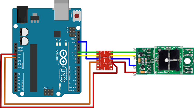
The logic level converter receives 5V (orange wire) and 3.3V (red wire) from Arduino Uno. The 3.3V voltage also goes to pin 8 of the H2S sensor.
GND (blue wire) runs from Arduino Uno to the logic level converter and then to the H2S sensor.
Pin 11 runs to the HV4 pin of the logic level converter. Its counterpart LV4 is connected to pin 2 (RXD) of the H2S sensor. Later, in the code, this pin will become SoftwareSerial TX.
Pin 10 runs to the HV3 pin of the logic level converter. Its counterpart LV3 is connected to pin 3 (TXD) of the H2S sensor. Later, in the code, this pin will become SoftwareSerial RX.
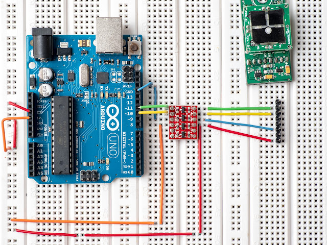
This is how the connections are made on a breadbaord. I used the same colors of wire as in the above diagram, to make things easier to follow:
If you don’t want to dig into the datahsheet of the sensor, here is a detailed image of the H2S sensor connector:

From top to bottom we have:
pin 1 – N/C
pin 2 – RXD
pin 3 – TXD
pin 4 – N/C
pin 5 – N/C
pin 6 – GND
pin 7 – N/C
pin 8 – V+ (2.6 to 3.6V)
H2S sensing with Arduino Uno: the code
The code is the same as in the original blog post, with only minor changes to accommodate SoftwareSerial:
This file contains bidirectional Unicode text that may be interpreted or compiled differently than what appears below. To review, open the file in an editor that reveals hidden Unicode characters.
Learn more about bidirectional Unicode characters
// SPEC H2S Sensor | |
// See https://electronza.com/h2s-sensing-revisited-tutorial-arduino-uno/ | |
// Serial number of my sensor | |
// #define mysensor_serial_no 012017030207 | |
// #define portOne_RX_BUFFER_SIZE 256 | |
// #define portOne_TX_BUFFER_SIZE 256 | |
// Sensor values | |
// The format of the output is: SN[XXXXXXXXXXXX], PPB [0 : 999999], TEMP [-99:99], | |
// RH[0:99], RawSensor[ADCCount], TempDigital, RHDigital, Day[0:99], Hour [0:23] | |
// Note that on Arduino Due integer variable (int) stores a 32-bit (4-byte) value. | |
// This yields a range of -2,147,483,648 to 2,147,483,647 | |
// (minimum value of -2^31 and a maximum value of (2^31) – 1). | |
// On 8 bit boards some readings have to be recorded as floats | |
// The big change: we use software serial for H2S sensor | |
#include <SoftwareSerial.h> | |
// software serial #1: RX = digital pin 10, TX = digital pin 11 | |
SoftwareSerial portOne(10, 11); | |
String SensorSerialNo; | |
long H2S; | |
long Temperature; | |
long RH; | |
long RawSensor; | |
long TempDigital; | |
long RHDigital; | |
int Days; | |
int Hours; | |
int Minutes; | |
int Seconds; | |
#define command_delay 500 | |
#define start_delay 2500 | |
String dataString = ""; | |
String responseString = ""; | |
boolean dataStringComplete = 0; | |
char inChar; | |
void setup() { | |
Serial.begin(9600); | |
Serial.println("H2S sensor demo code!"); | |
portOne.begin(9600); | |
// Normally, data is returned within one second | |
portOne.setTimeout(1000); | |
// reserve 80 bytes for the dataString | |
dataString.reserve(150); | |
responseString.reserve(150); | |
// Wait for sensor | |
delay(500); | |
flush_portOne(); | |
// EEPROM dump | |
SPEC_dump_EEPROM(); | |
Serial.println(" "); | |
Serial.println("STARTING MEASUREMENTS"); | |
Serial.println(" "); | |
} | |
void loop() { | |
// Do a readout every 10 seconds | |
SPEC_Data_read(); | |
SPEC_parse_data(); | |
SPEC_print_data(); | |
delay(10000); | |
} | |
/* ******************************************************************************** | |
* This function triggers one measurement and receives the data from the sensor | |
**********************************************************************************/ | |
void SPEC_Data_read(){ | |
// First, we do some initialization | |
// dataStringComplete is set as "false", as we don't have any valid data received | |
dataStringComplete = 0; | |
// Clear the data string | |
dataString = ""; | |
// Now we trigger a measurement | |
portOne.print(" "); | |
// We wait for the sensor to respond | |
dataString = portOne.readStringUntil('\n'); | |
//Serial.println(dataString); | |
} | |
/* ******************************************************************************** | |
* This function takes the received string and upodates sensor data | |
**********************************************************************************/ | |
void SPEC_parse_data(){ | |
// Parses the received dataString | |
// Data string is comma separated | |
// The format of the output is: SN[XXXXXXXXXXXX], PPB [0 : 999999], TEMP [-99:99], | |
// RH[0:99], RawSensor[ADCCount], TempDigital, RHDigital, Day[0:99], Hour [0:23], | |
// Minute[0:59], Second[0 : 59]\r\n | |
// Take a look also at | |
// https://stackoverflow.com/questions/11068450/arduino-c-language-parsing-string-with-delimiter-input-through-serial-interfa | |
// We look first for the SN | |
int idx1 = dataString.indexOf(','); | |
SensorSerialNo = dataString.substring(0, idx1); | |
int idx2 = dataString.indexOf(',', idx1 + 1); | |
// Hint: after comma there's a space – it should be ignored | |
String S_gas = dataString.substring(idx1 + 2, idx2); | |
H2S = S_gas.toInt(); | |
int idx3 = dataString.indexOf(',', idx2 + 1); | |
String S_temp = dataString.substring(idx2 + 2, idx3); | |
Temperature = S_temp.toInt(); | |
int idx4 = dataString.indexOf(',', idx3 + 1); | |
String S_humi = dataString.substring(idx3 + 2, idx4); | |
RH = S_humi.toInt(); | |
int idx5 = dataString.indexOf(',', idx4 + 1); | |
String S_raw_gas = dataString.substring(idx4 + 2, idx5); | |
RawSensor = S_raw_gas.toInt(); | |
int idx6 = dataString.indexOf(',', idx5 + 1); | |
String S_Tdigital = dataString.substring(idx5 + 2, idx6); | |
TempDigital = S_Tdigital.toInt(); | |
int idx7 = dataString.indexOf(',', idx6 + 1); | |
String S_RHdigital = dataString.substring(idx6 + 2, idx7); | |
RHDigital = S_RHdigital.toInt(); | |
int idx8 = dataString.indexOf(',', idx7 + 1); | |
String S_Days = dataString.substring(idx7 + 2, idx8); | |
Days = S_Days.toInt(); | |
int idx9 = dataString.indexOf(',', idx8 + 1); | |
String S_Hours = dataString.substring(idx8 + 2, idx9); | |
Hours = S_Hours.toInt(); | |
int idx10 = dataString.indexOf(',', idx9 + 1); | |
String S_Minutes = dataString.substring(idx9 + 2, idx10); | |
Minutes = S_Minutes.toInt(); | |
int idx11 = dataString.indexOf('\r'); | |
String S_Seconds = dataString.substring(idx10 + 2, idx11); | |
Seconds = S_Seconds.toInt(); | |
} | |
/* ******************************************************************************** | |
* This function prints the sensor data | |
**********************************************************************************/ | |
void SPEC_print_data(){ | |
Serial.println("********************************************************************"); | |
Serial.print ("Sensor Serial No. is "); | |
Serial.println (SensorSerialNo); | |
Serial.print ("H2S level is "); | |
Serial.print (H2S); | |
Serial.println (" ppb"); | |
Serial.print ("Temperature is "); | |
Serial.print (Temperature, DEC); | |
Serial.println (" deg C"); | |
Serial.print ("Humidity is "); | |
Serial.print (RH, DEC); | |
Serial.println ("% RH"); | |
Serial.print ("Sensor is online since: "); | |
Serial.print (Days, DEC); | |
Serial.print (" days, "); | |
Serial.print (Hours, DEC); | |
Serial.print (" hours, "); | |
Serial.print (Minutes, DEC); | |
Serial.print (" minutes, "); | |
Serial.print (Seconds, DEC); | |
Serial.println (" seconds"); | |
Serial.println ("Raw Sensor Data"); | |
Serial.print ("Raw gas level: "); | |
Serial.println (RawSensor); | |
Serial.print ("Temperature digital: "); | |
Serial.println (TempDigital); | |
Serial.print ("Humidity digital: "); | |
Serial.println (RHDigital); | |
Serial.println (""); | |
} | |
/* ******************************************************************************** | |
* EEPROM dump | |
**********************************************************************************/ | |
void SPEC_dump_EEPROM(){ | |
// First we trigger a measurement | |
portOne.print(" "); | |
// Within one second time we send the command "e" | |
delay(400); | |
portOne.print("e"); | |
dataString = portOne.readStringUntil('\n'); | |
// You can uncomment this line if you wish | |
//Serial.println(dataString); | |
for (int i=0; i<20; i++){ | |
responseString = portOne.readStringUntil('\n'); | |
Serial.println(responseString); | |
} | |
} | |
void flush_portOne(){ | |
// Do we have data in the serial buffer? | |
// If so, flush it | |
if (portOne.available() > 0){ | |
Serial.println ("Flushing serial buffer…"); | |
while(1){ | |
inChar = (char)portOne.read(); | |
delay(10); | |
Serial.print(inChar); | |
if (inChar == '\n') break; | |
} | |
Serial.println (" "); | |
Serial.println ("Buffer flushed!"); | |
} | |
} |
That’s all folks!
32 Comments
What is going on in your physical wiring with both the 5V and 3.3V pins from the Arduino going to the same outer rail track, and the red wire on the inner rail track connecting to the same inter rail? I’m throughly confused.
5v goes to outer rail
3.3v goes to inner rail (the angle of the wire is a bit misleading)
on breadboards from wishay the rails are split in half, tbat’s why the short red wire connecting the inner rails
So the 3.3v pin from the Arduino is going to the inner track? Now that makes sense.
If one were to use a nodencu or similar ESP8266 3.3V device, there would be no need to use a logic level converter, right? And if it has WiFi you wouldn’t have to bother with even using SoftwareSerial as you could use MQTT or webhooks to display your output.
For anyone wondering, the reason you need to use this logic converter is because the RX/TX pins work on 5v, which will fry your sensor. It’s probably easier to just get a 3.3v controller and use that.
Hi.
What should I add to the program source to measure ozone gas?
First, you need an ozone sensor. Then, you add the code according to the sensor you decide to use.
110406 O3 1801 I have an ozone sensor.
I would like to know what code to add to use this ozone sensor.
If you just throw some numbers here I won’t be able to help you. Be more specific – link to manufacturer’s page, datasheet, etc.
Sorry.
The company is SPEC SENSORS. We will link the data sheet.
https://www.spec-sensors.com/product/ozone-o3-sensor-20-ppm-pinned-package/
You have three different products:
– sensor only. My advice is to avoid it, as it’s nearly impossible to build the required analog front-end at the hobbyist level
– sensor + analog front-end (https://www.spec-sensors.com/product/ultra-low-power-analog-sensor-module-ozone/). You can read the output voltage with an A/D converter, but you will also have to do some computations to compensate for temperature and humidity.
– sensor + digital board (https://www.spec-sensors.com/product/digital-gas-sensor-ozone/). Just like the one I used in the H2S sensing blog post. The most expensive, but also the easiest to use. Just read the digital values.
Thank you for your question.
Currently, the parts I have are sensors + digital boards.
You told me to read the digital value. Then, in the above code,
I want to know.
1. long H2S; -> long O3;
2. Serial.println (“H2S sensor demo code!”); -> Serial.println (“O3 sensor demo code!”);
3. H2S = S_gas.toInt (); -> O3 = S_gas.toInt ();
4. Serial.print (“O3 level is”);
5. Serial.print (O3);
Really cool project – are the data you measure accessible somewhere and did you test it for Bad breath detection?
I had the sensor installed in an outdoor air quality moitoring station – https://electronza.com/diy-air-quality-monitoring-station/. But I took the whole thing offline for the winter season, and I plan to put it back online next spring, after I will solve some minor issues in software.
Thank you for your posting.
I have one question. What kink of wire you used for connection?
I have one but it is so weak to connect each other.
Hi Jo,
Any type of jumper,wire will do. https://www.sparkfun.com/products/8431 will work fine.
In my project I used some wires from a kit like this https://www.sparkfun.com/products/14671 as they look better in the pictures.
Thank you for reply.
I bought all of things you used above and assembled.
Unfortunately, it didnt work when i upload code to arduino uno. I dont know why….and it seems to be wrong that mismatch rx pin between in the picture and code you wrote (dgs h2s sensor used rx pin 2nd place where green wire stuck to digital 11, but code used 10 for rx)
Can i ask why you used level converter though arduino uno can provide 3.3v output? Is it important?
Regards.
Arduino Uno can provide 3.3V power, but it uses 5V logic levels. That means, on (software) TX and RX pins you will have 5V for logical “1”. The H2S sensor uses 3.3V logic, thus the need for the logic level converter.
If it doesn’t work, you can try to swap TX and RX lines.
Okay. Thank you! I will try it!
TEODOR
Thank you for taking the time to write this. I was thinking of making a similar project but I dont have the programming skills for it. I appreciate that you made public your efforts
Thanks!
First of all, thank u for this tutorial!
Well, i’m having some issues with my project…
My sensor keeps returning no data, no matter what i change on it…
Everything is the same as is described in your tutorial, but the final results aren’t
Thanks again!
Hi Breno,
The easiest thing to do is run the SerialPassthrough sketch and communicate directly with the sensor. Try to send a c character, that should trigger a new measurement and you should see some output. If not, check connections. Also, try to reverse the RX and TX lines.
Also, please observe that not all Arduino pins can be used with SoftwareSerial. See the library notes on https://www.arduino.cc/en/Reference/softwareSerial. My choice of pins 10 and 11 is not random.
You may also wish to take a look to this new DGS sensor library: https://github.com/SPEC-Sensors/DGS
I’m using Arduino Pro Mini 3v3.
I have created an application to zero the sensor after a time (configurable).
I have uploaded the code and documentation to github.
https://github.com/VikIborra/SPEC-Sensors/tree/master/DGS/AutoCalibrateZero
Nice!
thank you for this tutorial! …
I have one question which of gas sensor gives accurate results for H2S gas. ?
Hello Arkan,
To my best knowledge, the DGS-H2S is reasonably accurate and it’s relatively cheap. That makes it interesting for hobbyists and for citizen science projects.
Obviously, there are better sensors out there, but they are at least one order of magnitude more expensive, or they require some dedicated analog front-ends which are difficult to build by the average maker.
You can take a look at:
http://www.nemoto.eu/nap-520.html
https://www.wpiinc.com/var-iso-h2s-flexible-hydrogen-sulfide-sensor
https://www.gas-sensing.com/replacement-sensors/aeroqual-hydrogen-sulfide-sensor-0-10-ppm-ehs.html
and there are many more…
Hii,
I am using Spec sensor NO2 968-043.
I am unable to get data.
Please, provide me with sufficient suggestion.
It should work the same as the DGS-H2S Sensor. You can also try the SPEC Arduino library: https://github.com/SPEC-Sensors/DGS
What is the difference between Digital and Analog gas sensor for h2s spec sensor.? How to use the sensor without module. Because the sensor cost is high with module.?
The digital version returns the H2S concentration already computed (in ppb). The analog version returns a voltage that is proportional to the H2S concentration. You will have to compute the gas value in ppb yourself.
The sensor itself is an amperometric sensor, its output is a current proportional to the gas concentration, in the uA range. Thus, you will need an analog front-end to convert that current into a voltage, which you can later apply to an ADC input.
Hi,
I have an SO2 Sensor + digital board from SPEC Sensors and I assume the setup would be the same. I also want to incorporate 2 LEDs and a buzzer as an alarm into the setup. How shall the circuit vary and what do I need to be careful about and consider?
How significantly will the programming (code) change (if…else statements I presume) if those are incorporated.
Thanks!
The code should work for SO2 too. The changes to the code are small.