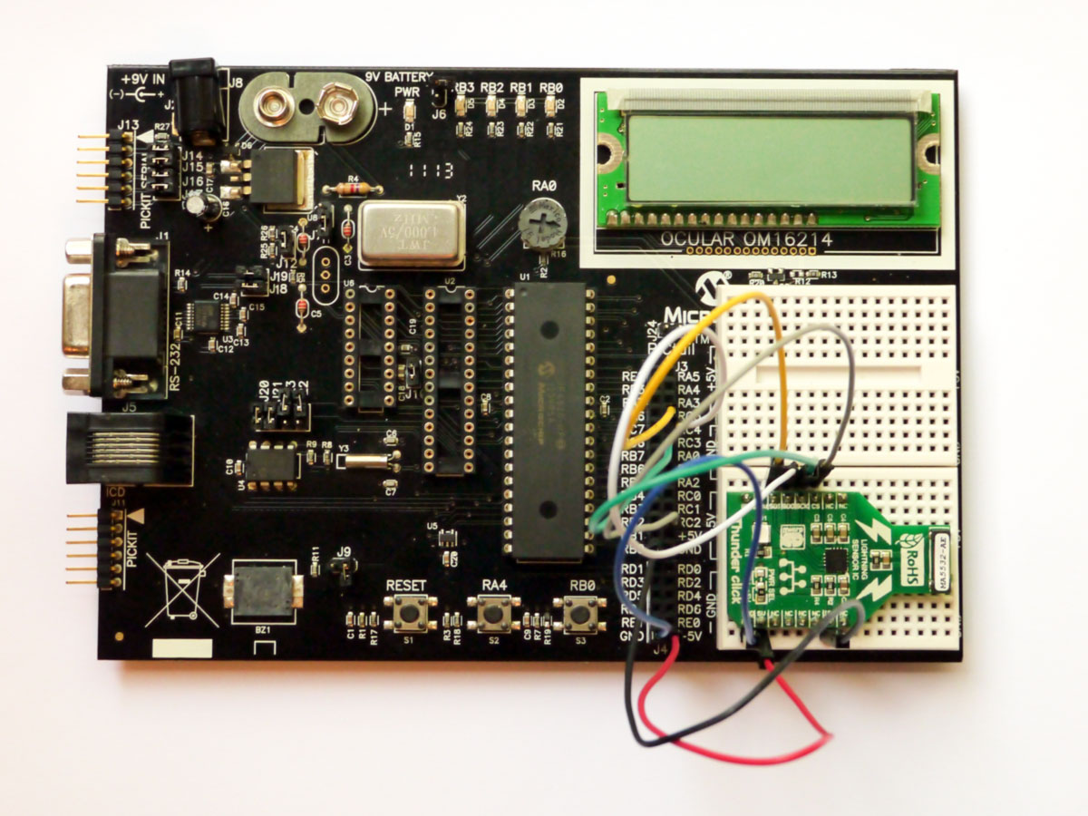
The article about lightning detection using Arduino and the AS3935 sensor quickly became the most accessed blog post. Today I will take a step further and write about lightning detection on 8-bit PIC microcontrollers. The hardware I will use is a PICDEM2 Plus demo board from Microchip, equipped with a PIC18F4520 microcontroller, and a Thunder Click board from MikroElektronika.
The PICDEM2 Plus is a 5V demo board, so the microcontroller used should be able to work on 5V power and should be in 40-pin PDIP capsule. Second, the microcontroller used should have hardware SPI. Software SPI will not work, as the software SPI library will conflict with the ISR routine for lightning detection. I do prefer a PIC microcontroller from the high-range PIC18 range, as those microcontrollers are able to perform hardware multiplication and work faster in this application. Considering those constraints and what I already had in my parts box, my choice was the PIC18F4520. The Thunder click is modified to work on 5V voltage, similar to the Arduino example.
By using the PICDEM2 Plus demo board there are several constraints that must be met:
- LCD is connected to PORTD, with LCD power being controlled by pin RD7, and R/W line connected to pin RD5, instead of being grounded as it is usually done.
- the INT pin of the AS3935 is connected to pin RB0, which corresponds to external interrupt INT0.
- SDI pin is RC5
- SDO pin is RC4
- SCK pin is RC3
- CS pin is connected to RC2 (not critical).
There is also an LED connected to pin RB0, so the jumper J6 on the
PICDEM2 Plus demo board must be disconnected. The button connected also
to RB0 cannot be disconnected, and this is a big issue since the button
comes also with a pull-up external circuit which will interfere with the
way AS3935 interrupts works. There is no other way than to physically
remove R19, thus disabling the button.
I used an external 4MHz external oscillator. This is not critical, but remember to change the CONFIG registers if you use another option. I would not suggest the internal oscillator though, as a precise clock frequency is needed when performing the AS3935 calibration.
With the above considerations, the connection diagram is at follows:
MikroC code for PIC18F4520
The code is heavily inspired by the PIC32 example from Libstock. Actually, most functions from the PIC32 example work directly with the PIC18F4520.
The following (important) settings were made in the CONFIG registers:
– EC oscillator, port function on RA6
– Watchdog timer disabled
– CCP2 multiplexed with RC1
– PORTB A/D disabled
– Extended instruction set disabled. I don’t know why, but if I enable this nothing works anymore.
What I have added is a calibration function. This is extremely important, as a correct calibration has a great impact on the success of lightning detection. To perform the calibration, in AS3935 we must set LCO_FDIV = 00, which corresponds to bits 7:6 of register 0x03. Then, we must set DISP_LCO = 1, which corresponds to bit7 of register 0x08. At his point on the INT pin, we should have the LCO frequency divided by 16.
Next, we use TIMER1 to count the pulses coming from the INT pin over a 100ms period of time. Considering an optimal frequency of 500KHz, divided by 16 it gets 31250 Hz. Over 100 ms we should have 3125 if the sensor is calibrated correctly. So, we swap all the range of calibrating capacitor by altering bits 3:0 of AS3935 register 0x08, we measure the LCO frequency, and we choose the closest value to 3125.
The AS3935 datasheet specifies a 3.5% maximum deviation from this frequency for the sensor to work. 3.5% of 3125 is 109. So, we check if the difference between the desired frequency and the measured frequency is greater than 109. If it is, then we display “Calibration error” and we enter an infinite loop.
The main program displays some internal parameters of AS3935, then it re-enables external interrupts and starts monitoring the AS3935. A counter and a “Waiting…” message is displayed if nothing happens, so I know that the whole thing is not stuck :). If an interrupt occurs, then we read the content of bits 3:0 of register 0x03, and we check against the interrupt codes.
If Reg 0x03 is 0001, then we have noise. If Reg 0x03 is 0100 then we have disturbers (man-made perturbations). If Reg 0x03 is 1000 than we have lightning. In this case, we read also the content of bits 5:0 in register 0x07 and determine the distance to the lightning event.
The code is not optimized, and I know that for some variables I’m allocation more memory space than needed. Second, the LCD size is a big limitation, as I can’t display much information on it. In the future, there will be a better version for 4×20 lines LCDs, and maybe with an audible alarm for approaching storms.
This code is still in its alpha version, so please feel free to post in the comments section any mistakes you find in this code.


0 Comments